
Ancheer Electric Bike Wiring Diagram
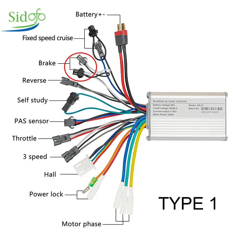
The rated voltage is 36 to 48 Volts. The rated power is 500 Watts with phase angle self-study and the throttle voltage is from 1.1 to 4.2 volts. So, with this Ebike Brushless Motor Controller you can control almost all types of BLDC motors which are up to 500 Watts and 36 to 48 volts. Motor three phases Green, Blue, and Yellow.

Dualtron Controller Wiring Diagram
Creating an electrifying ride, the 36-volt e-bike controller wiring diagram unveils the intricate web of wires, signaling a connection between power and performance. Like an artistic masterpiece, this unassuming diagram ignites the sparks of curiosity, shedding light on the secrets of an e-bike's inner workings. Finally, the jigsaw puzzle of wires takes shape, unraveling a symphony of efficiency.
GREENTIME 36V/48V 500W/600W 30Amax BLDC Motor Controller Electric Bike Tricycle Controller Driver
View and Download E-Bike 36V service manual online. Bicycle. 36V bicycle pdf manual download.. Performance Specifications* Item Specification Top speed 17.5 mph @ 36 volts in "P" Performance mode. 12.5 mph @ 36 volts in "E" Economy mode. Maximum grade Over 12% with a 200 lb. rider plus load.. Wiring Diagram Wiring Diagram 8-12.

Flora Wireworks Ebike Display Wiring Diagram Schematic Images скачать оперу
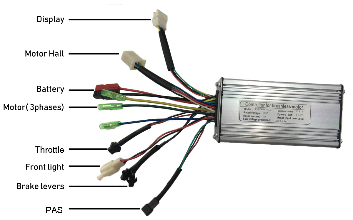
The electric bike controller is one of the main parts of an electric bike, it is the brain of the e-bike, controlling the motor 's speed, start, stop. It is connected to all the other electronic parts such as the battery, motor, and the throttle (accelerator), display (speedometer), PAS or other speed sensors if exist.

36 Volt Controllers Wiring Diagrams Wiring Diagram AME Electric Bicycle Kit, Electric Car
A 36 volt e bike controller wiring diagram is an invaluable tool that helps owners and mechanics understand the electrical components of an e-bike system. It provides a comprehensive overview of the wiring configuration and is essential for performing basic maintenance or repairs. Familiarizing oneself with the components and their respective.
e bike controller wiring diagram Wiring Diagram and Schematic Role
Wiring Diagram Pictures Detail: Name: 36 volt electric scooter wiring diagram - The speed controllers wiring directions will precisely indicate which wires to connect to which parts and ponents Wiring an electric scooter bike. File Type: JPG. Source: support.electricscooterparts.com. Size: 82.10 KB.

Electric Bike Controller Circuit Diagram
Connect the battery. The first step in wiring your ebike controller is to connect the battery. Locate the positive (+) and negative (-) terminals on the controller and connect the corresponding wires from the battery. Ensure the connections are secure and there is no risk of short-circuiting.

Electric Scooter Controller Wiring Diagram перевод Neve Cabling
With everyone using similar 4:1 and 5:1 harnesses, I wonder why would someone make a limited run of somethinmg different. 1. Battery - from controller to display. 2. Start - this comes from display and goes to battery voltage when display turns on. 3. Ground - goes to throttle and display. 4. Tx Data from display to controller.
electric bike controller pdf
The controller comprises different wire colors such as yellow wire, black wire, green wire, etc. Here are a few steps to connect your e-bike controller connectors to the entire system: 1. Ensure You Have The Power Connectors Set Up Properly. The power connector has 3 wires; the two large wires are the positive (red) and negative (black) wires.

36 Volt E Bike Controller Wiring Diagram Wiring Schematic and Diagram
An e-bike controller is an electronic device that is an essential component of an electric bike. It acts as the brain of the e-bike system, controlling and managing the flow of electric current from the battery to the motor. The 36-volt e-bike controller specifically refers to the type of controller designed to work with a 36-volt battery system.

36 Volt E Bike Controller Wiring Diagram Esquilo.io
E-brakes. Whoever invented ebike safety etiquette has decided that an E-brake is critical safety equipment on an electric bike. Basically an E-brake means when you hit one of the brake levers, the motor power is momentarily cut off…this makes it hard to accidentally hit your brakes and the throttle at the same time.This requires (of course) two more sets of wires going from your controller.

36 Volt Controller Wiring Diagram
Step 4: Connect the Throttle. Next, connect the throttle to the controller. The throttle's wiring will typically consist of three or four wires: positive, negative, signal, and possibly an additional wire for power or lights. Follow the wiring diagram to ensure that the throttle is connected correctly.

Electric Bike Controller Wiring Diagram
Electric Bike Controller Wiring Diagram: An In-Depth GuideIn recent years, electric bikes have grown increasingly popular as a convenient, environmentally friendly form of transportation.. تفسر مم وبخ 36 Volt E Bike Töltő Schematic Seadomrep Com. Categories Wiring Diagram. Weil Mclain Cga 5 Wiring Diagram. Wiring Diagram 3 Way.
Ebike Controller Wiring Diagram ubicaciondepersonas.cdmx.gob.mx
When it comes to wiring the controller, it is essential to follow the manufacturer's instructions and guidelines. Each controller may have specific wiring requirements, so always refer to the manual provided by the manufacturer. 2. Components of the Controller. A 36 volt e bike controller typically consists of several components:

Bike Wiring
By following the diagram, technicians and DIY enthusiasts can ensure the safe and efficient operation of an electric bike. Step-by-Step Guide to Wiring an Ebike Controller. 1. Gather all the necessary materials: an ebike controller, a wire harness, a throttle, a battery pack, and any other accessories you may need. 2.
36 Volt E Bike Controller Wiring Diagram Wiring Harness Diagram
36 Volt E Bike Controller Wiring Diagram. Effectively read a wiring diagram, one has to find out how typically the components within the system operate. For instance , if a module is powered up and it sends out the signal of half the voltage and the technician would not know this, he would think he provides a problem, as he would expect a new.
